High-Pressure Oil Injection system High Pressure Oil Pump disassembly photos.
This 2001 DT466E digested a Babbitt bearing that used to be in contact with the crankshaft.
Engine was fully disassembled and rebuilt, but still would not fire.
We determined that there was only 70PSI of pressure on the output of the HPOP - in other words,
just engine oil pressure.
useful test to do is to blow shop air in the outlet or the inlet. If there is a huge quantity of blowby then you probably have problems.
See a Video of this test.
So we disassembled the HPOP unit and found that there were inside the pump bits of a brassy
colored metal as well as bits of a soft non-magnetic silvery metal, assumed to be Babbitt.
We further discovered that fine particles of Babbitt had become fused to the cylinder walls in the brass cylinder
core in the HPOP swashplate pump cylinders.
All of the swashplate pump pistons in the HPOP were jammed in the pushed-in position because of the Babbitt
buildup was so thick. We used a drift punch to pound them back out from the valve face side. This is why
there was so much blowby - with all the springs compressed, the brass pump core had nothing holding the sliding
valve face to the inlet/outlet ports in the pump body.
We also discovered that one of the swashplate pump cylinders had a crack running the full length on the inner wall,
but not on the outer wall.
So we scraped off the Babbitt from the swashplate pump cylinders, sanded them out with fine sandpaper, cleaned, and
re-assembled it.
The truck then started up just fine and does run, although sometimes it doesn't want to start right away.
I have no doubt that the pump is working at a fraction of its designed pressure because of all the enlarged
clearances due to the ground up bushing going through as well as the scraping and sanding we did to get it
operating smoothly again.
Because we had some difficulty finding instructions on disassembly or an exploded diagram, we took a few
quick pictures and post them here for future explorers.
These are not instructions. These are just some clues based on our experience.
Getting it apart was a bit hard, but here's a general guideline:
Remove the gear. Ours has a regular right-hand threaded bolt that's tight.
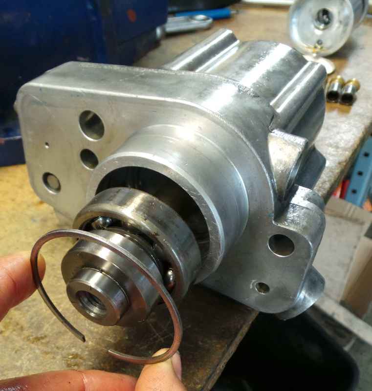
Remove the oil seal on the input shaft, and the snap ring behind that which holds in the main bearing.
Of course remove the fuel pump that goes on the other end.
Use an appropriate puller to remove the fuel pump cam lobe from the main shaft.
You can now either press out the main shaft by pressing on the end opposite the driven end, or
by using a bearing puller to pull the rear bearing, which was very tight on the shaft but only snug in pump housing.
Now you can press the shaft out if not already removed.
Now you need to get out the machined fixed position swashplate. We used some slide hammer puller and a lot of effort.
Then it comes all apart, and everything should fall lose in your lap so be ready for parts to go everywhere.
Note that pulling it apart with the tools we had dinged up the aluminum swashplate holder plug (the piece we slide
hammered out) so we had to clean up the burrs and wash it off before re-assembly, but it's not an important place so it
did not hinder the operation of the pump.
Getting it back together was pretty much the reverse disassembly except we used the bearing press to force the
swashplate plug back into the pump housing.
Heavily oil pistons, springs, and all moving parts with new crank case oil before assembling. VERY IMPORTANT.
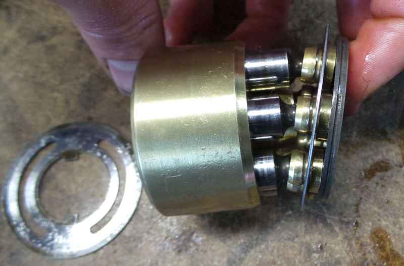
Put all the springs and pistons back in the brass cylinder core, with the piston collar and snap ring in place.
Put the cylinder+piston assembly in place with the piston cam cup plate on the swashplate plug.
Use one of the fuel pump mounting bolts inside the brass cylinder core and a spacer (like a socket) and a nut to
hold the pistons and cylinder and swashplate all together.
Align the swashplate rotationally correctly. If you get it 180 degrees out it will pump backwards. If you get it 90
degrees out, it will not pump at all and may self destruct. See pictures for orientation.
Double check rotational alignment and press into pump housing, till it's exactly flush.
Assemble all the other bits and pieces.
Note: On this unit,the pump turns counter-clock wise when looking at the gear end. Yes, really. This struck me as odd since the
gear was not keyed, and it's a right hand threaded bolt that holds it on. If it comes loose, it will screw right off of there and the gear
will fall off into your timing gears and get ground up. So be sure to get the gear retainer bolt tight enough!
We did not want to believe the pump turned counterclockwise, but the wear pattern on the gear indicated it, and so we shone a flashlight
in the hole on the engine and cranked it -- and sure enough, the teeth on the driving gear moved down, which means the pump turns counter-clock
wise.
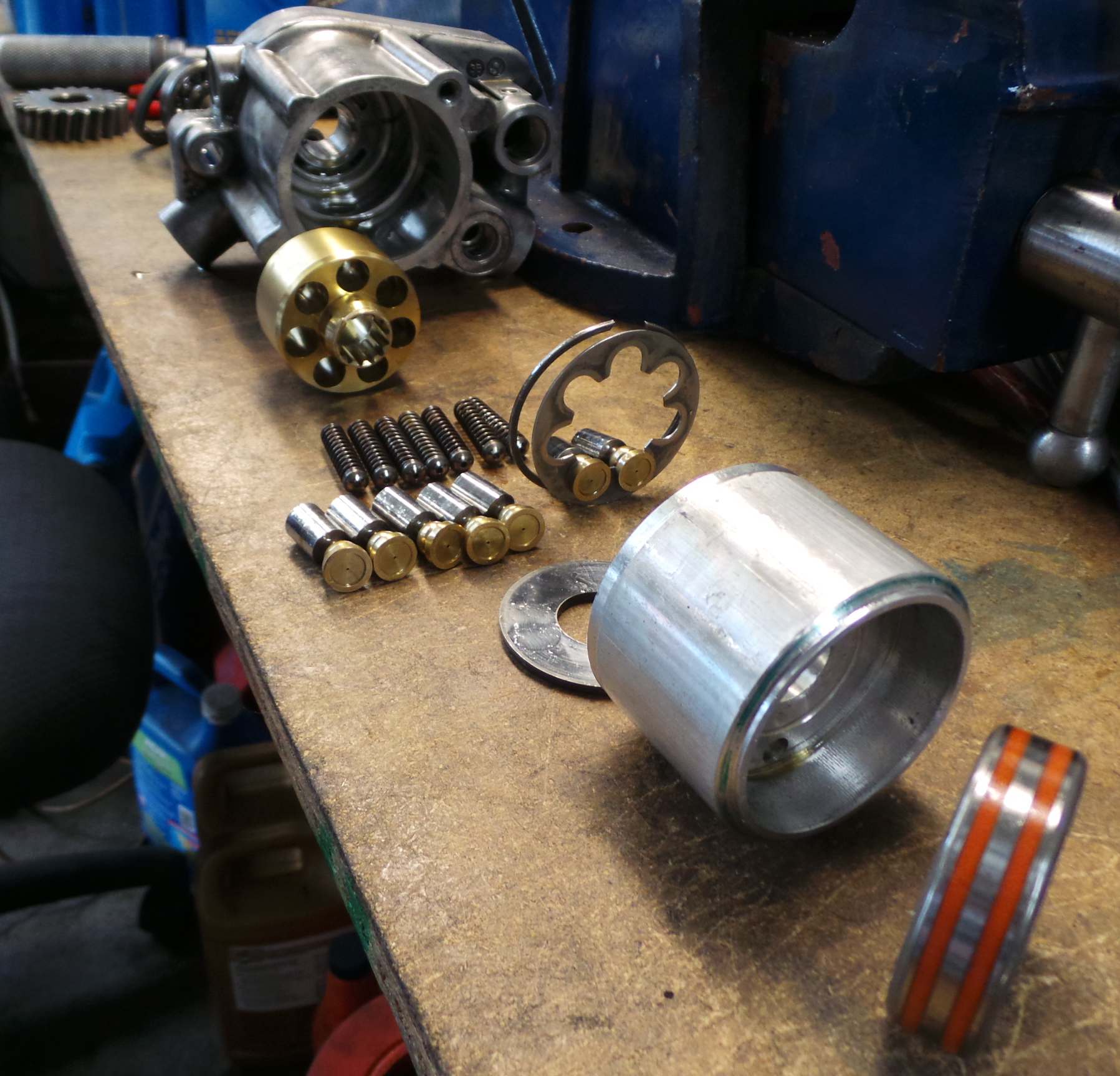
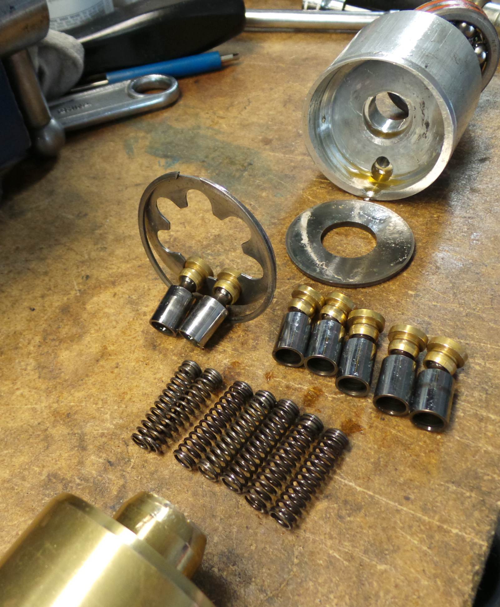
Without further boring details, here are the pictures. They are sort of haphazard but are intended to be set out in sort of
an exploded parts view.
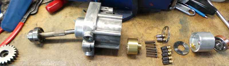
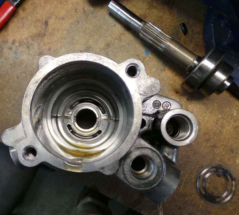
Above:
Left to right: Gear, Shaft, Main bearing, pump housing with steal valve seat still inside, brass cylinder core, piston springs, pistons, piston
collar retainer snap ring, piston collar, hard steel piston cup raceway plate, aluminum swashplate plug, rear bearing which inserts into swashplate plug.

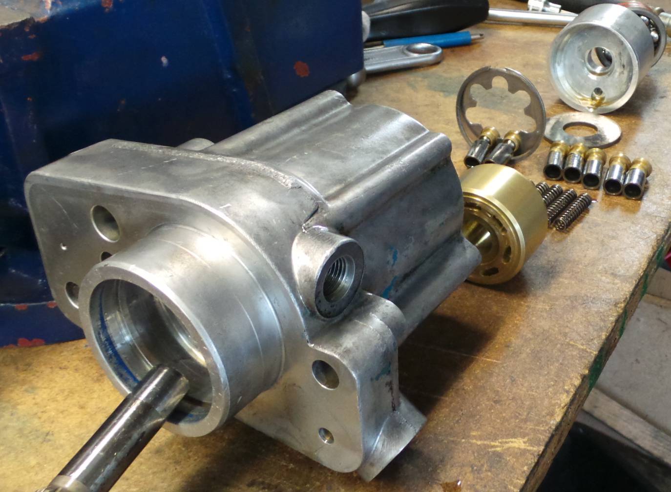
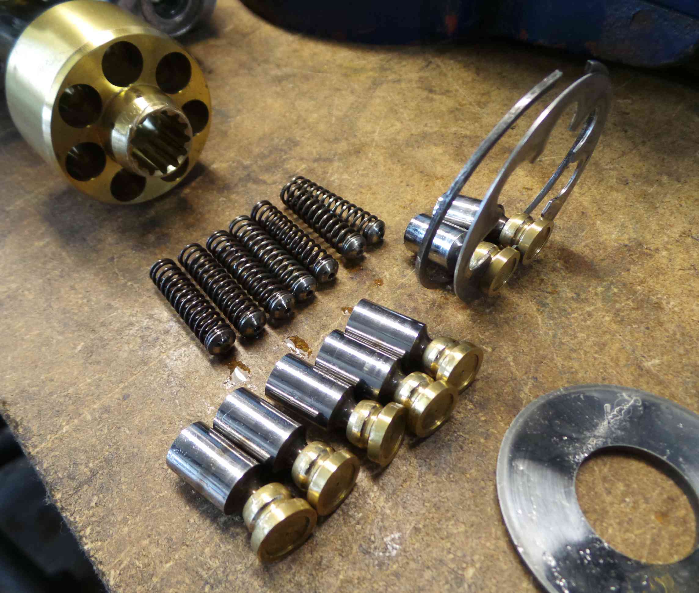
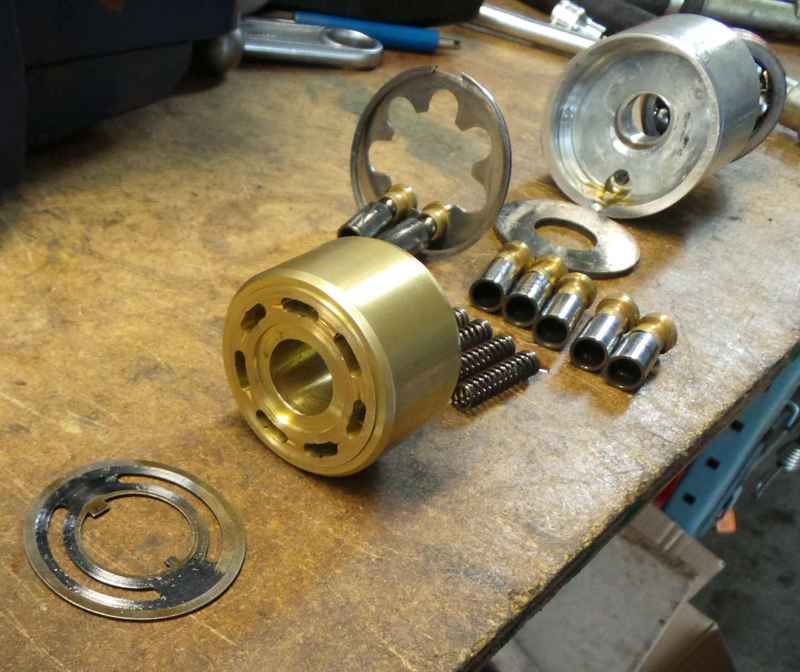
Above:
Another exploded view. That bearing goes into that aluminum swashplate endplug.

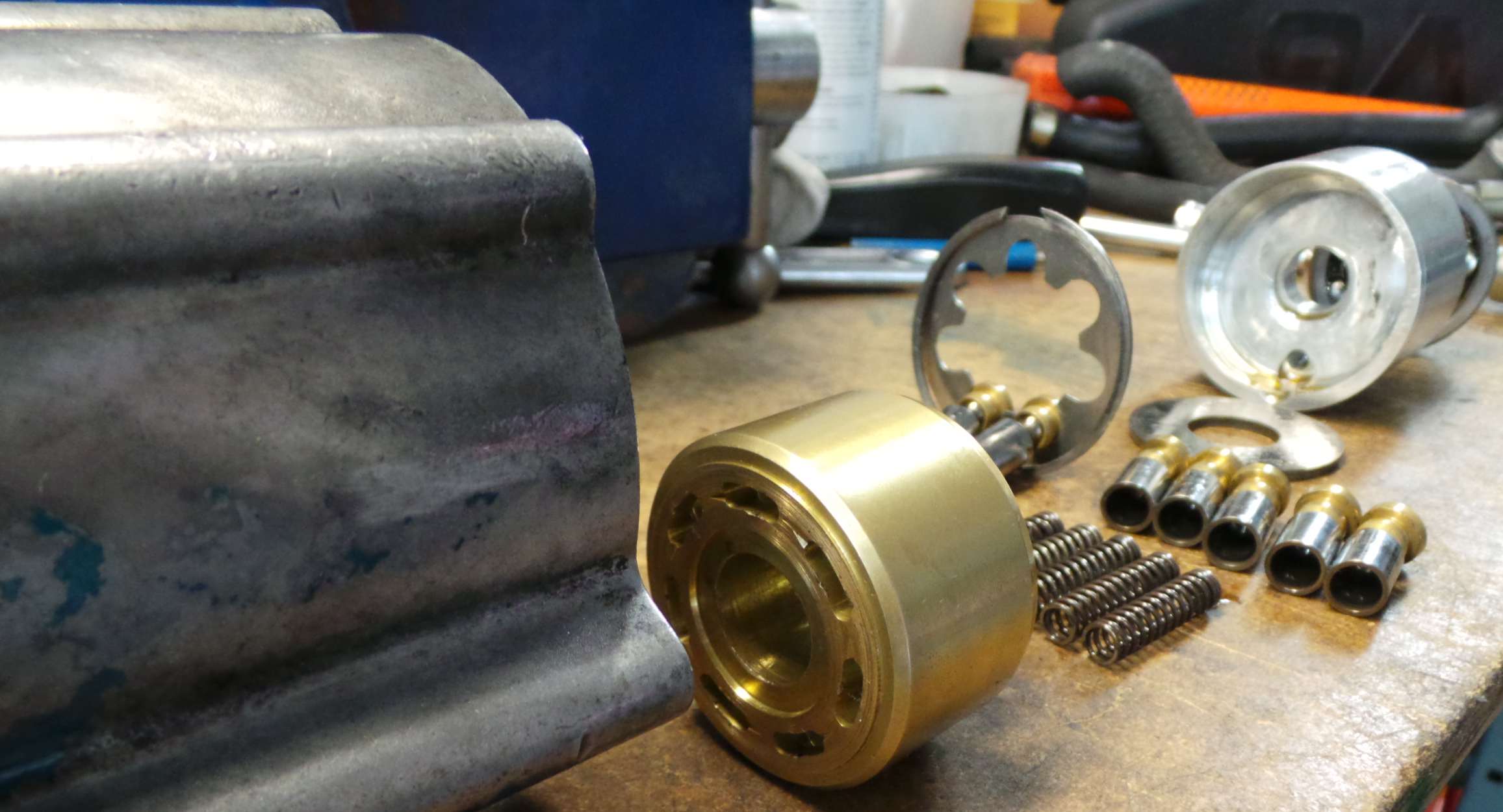
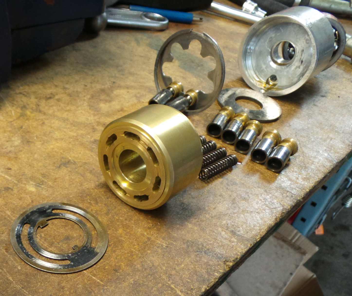
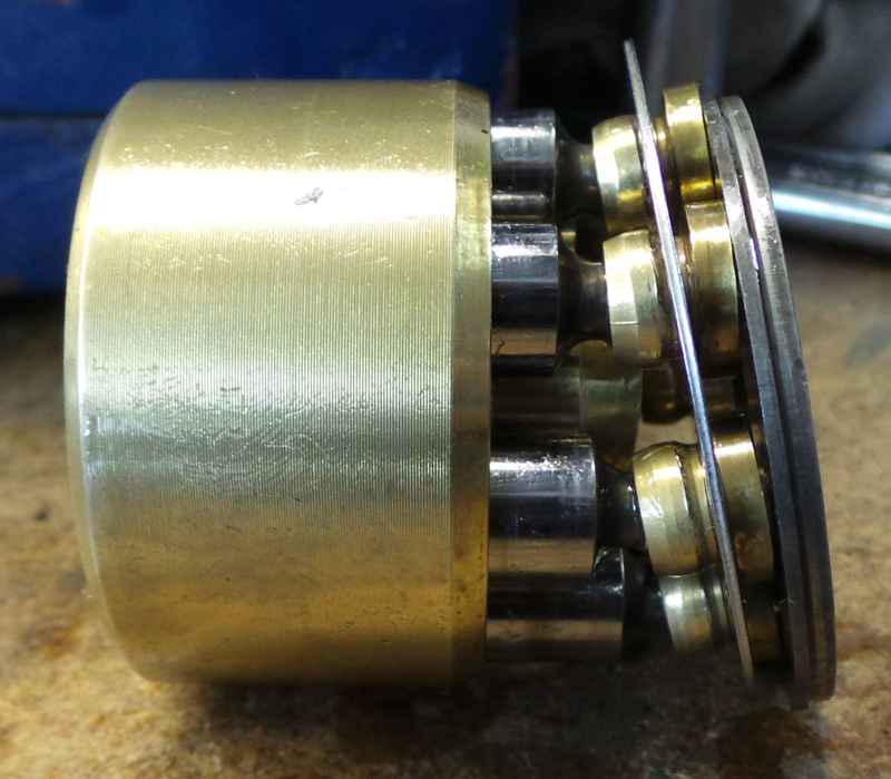
Above:
Another exploded view.

Above:
More of same.

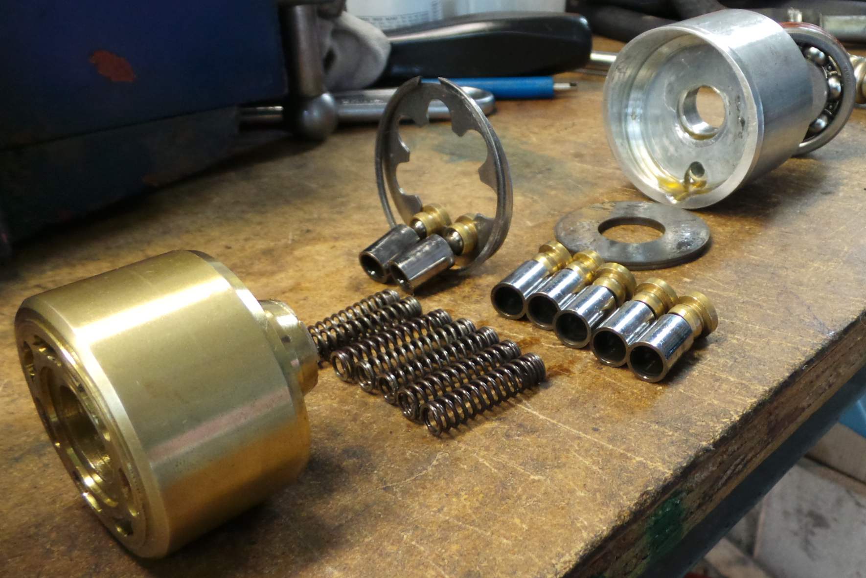
Above:
Cylinder and pistons and swashplate plug.

Above:
More of same.

Above:
More. Hey. When you work as hard at getting something apart as we did, you take extra pictures.
Above:
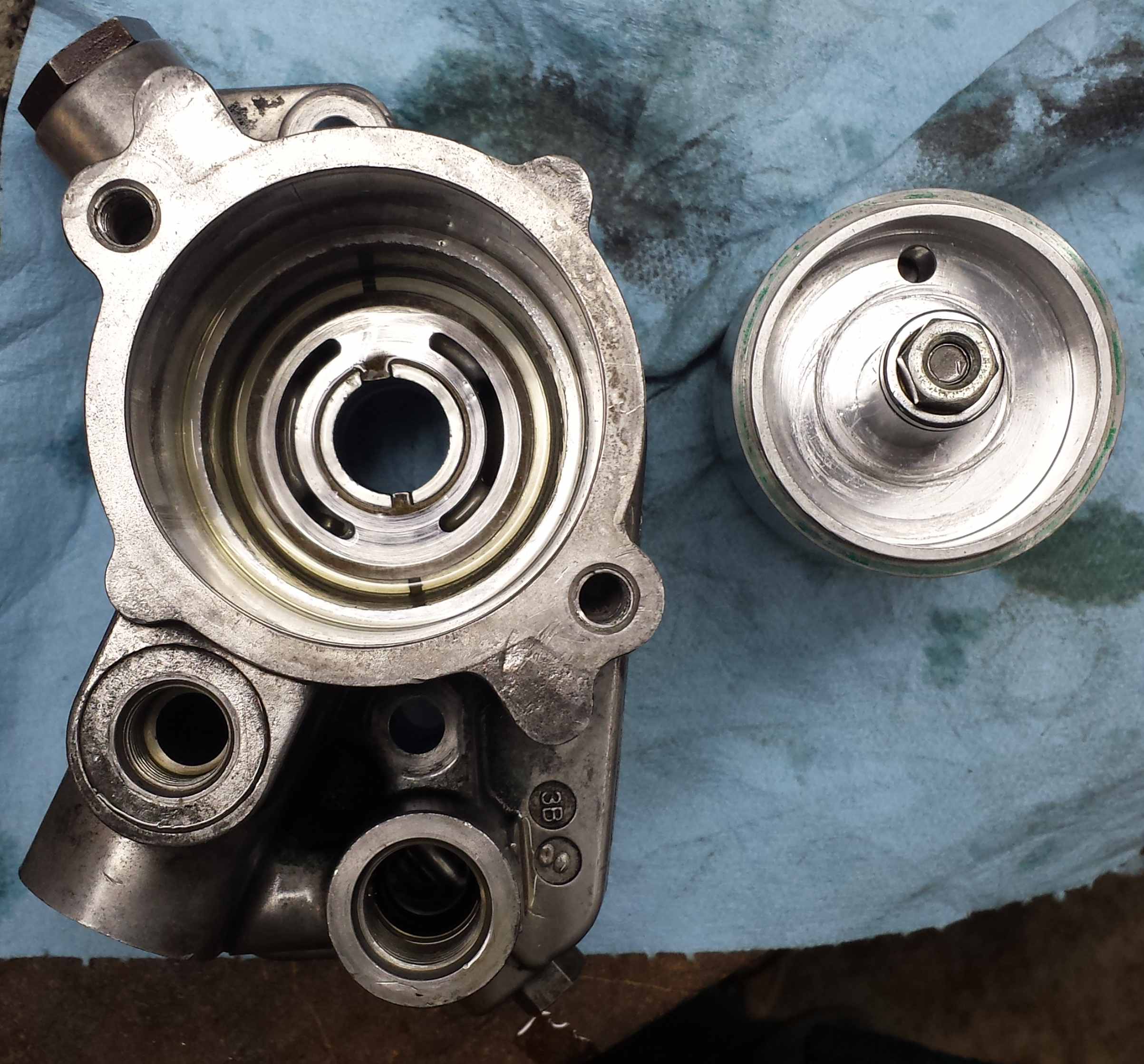
Here we also show the steel valve plate which goes in the pump housing, against which the rotating brass cylinder core presses. This is the valve seat.
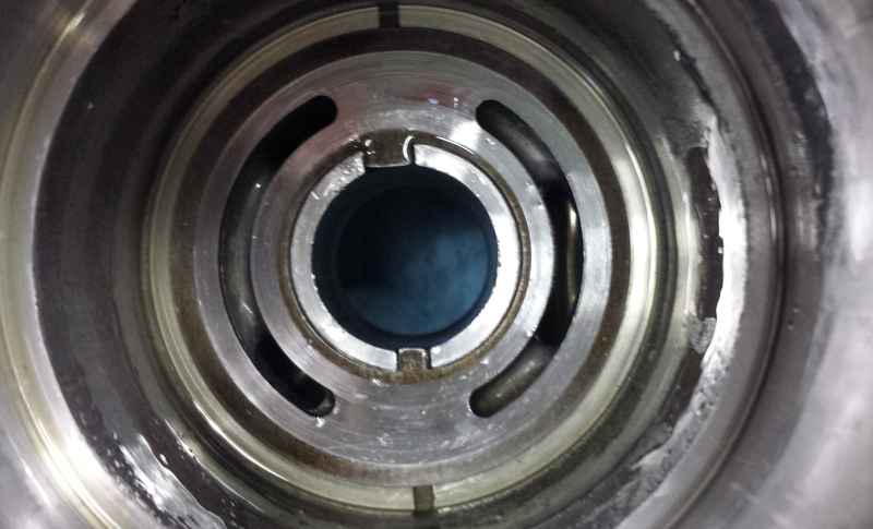
Above:
Here is where the thin steal valve seat locks into place in the pump housing. Nothing holds it but it is keyed so cannot rotate.
Above:
Again.
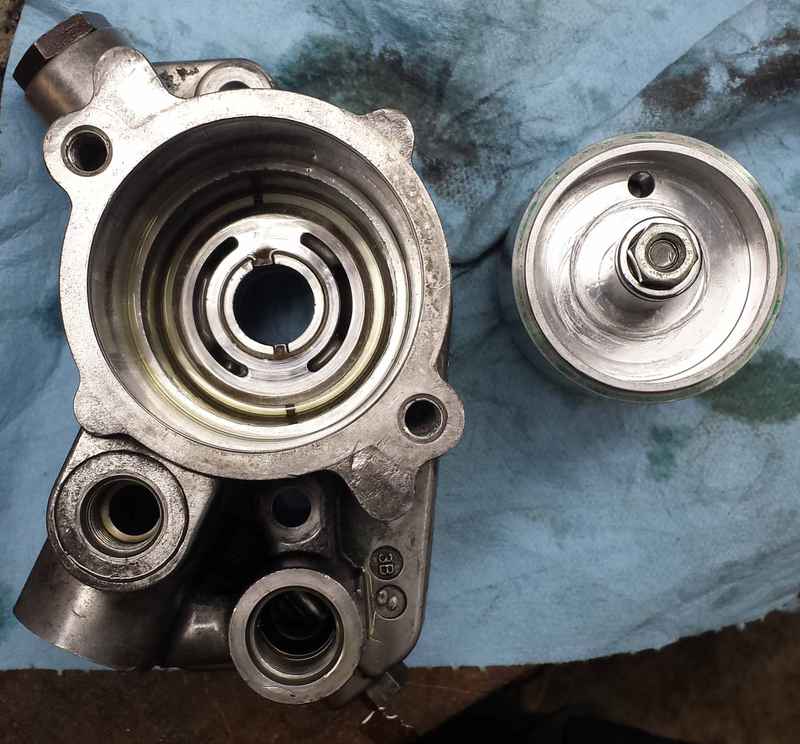
Above:
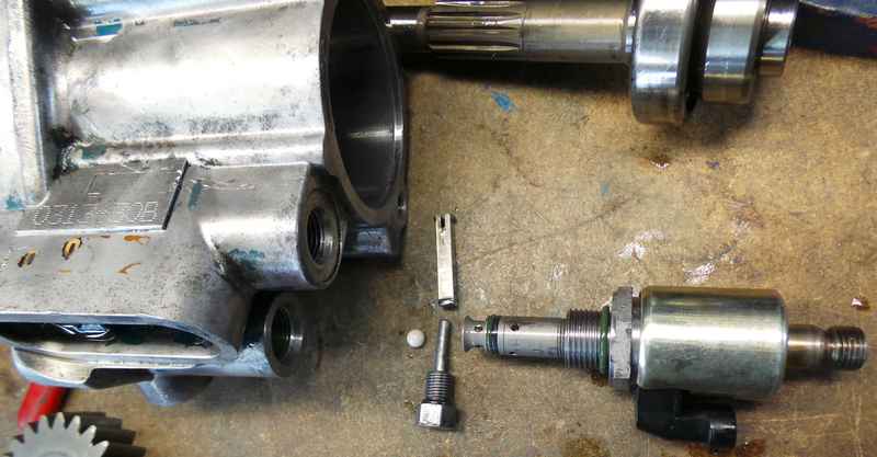
Here we see the IPR (Injection Pressure Regulator) which controls the output pressure by allowing oil pressure to bypass.
Also shown is the little white check valve ball which goes in the IPR hole, all the way down. It allows engine crank case oil pressure to
bypass the swashplate pump and flood directly into the high pressure oil galley. Once the swashplate pump starts pumping then the ball closes the check valve
and then real high pressure can be produced. If you don't put that ball in, all your high pressure oil will shoot back into the timing gear area and you won't
get good high pressure.
Above:
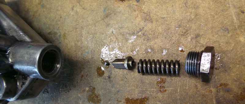
Pressure limiting bypass valve. If the output pressure goes above a certain pressure, then it pushes this ball against that spring and lets the excess pressure
to go free. I don't know whether this is a safety in case the IPR sticks shut or if this normally operates in bypass mode. Also absolutely vital to have that
ball and spring in there, otherwise you get no high pressure.
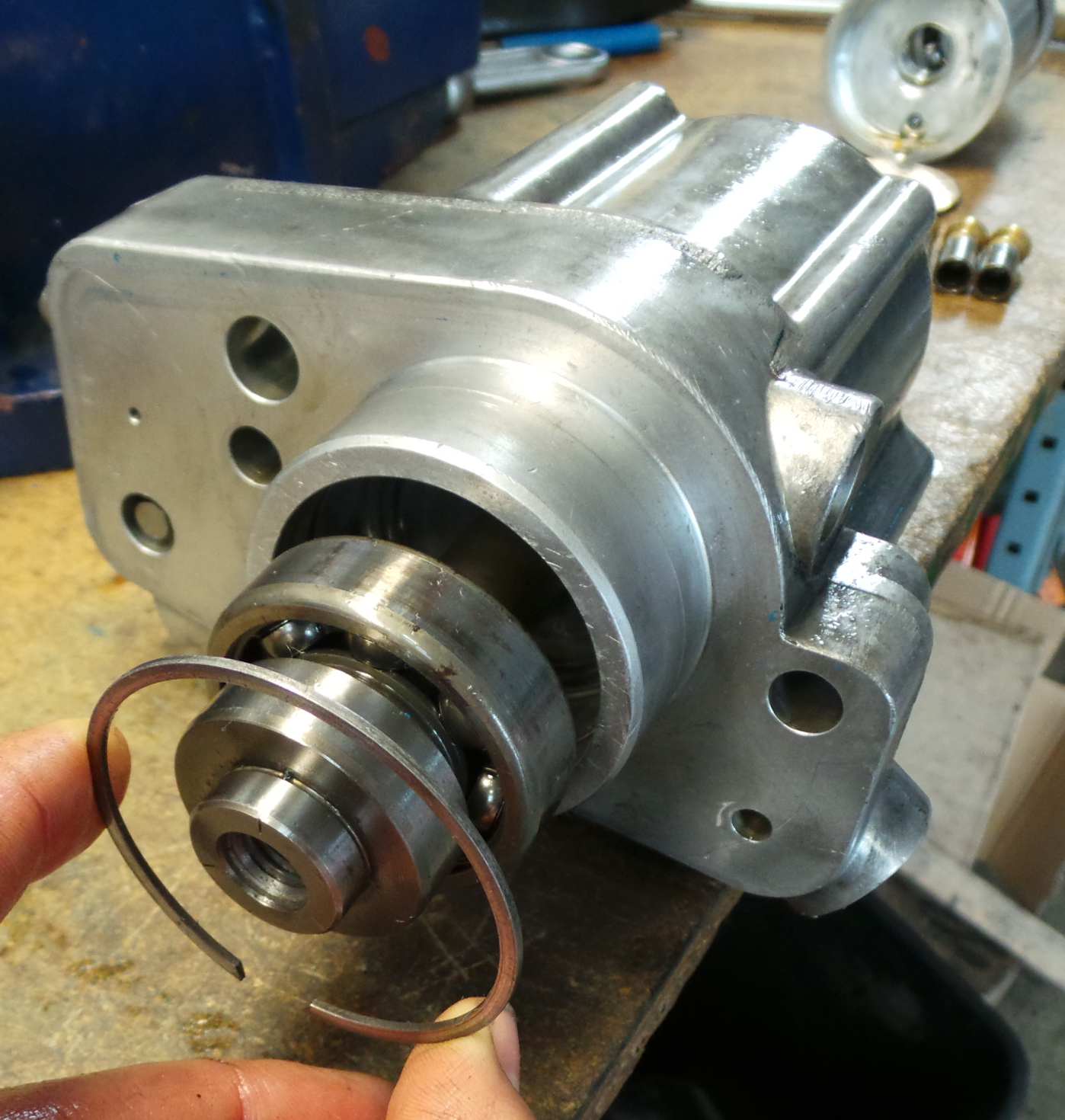
Above:
Shows how a snapring holds in the main bearing. Note that I was using the swashplate collar retainer snapring for the photo. However, the actual snapring was
the traditional type with an eyelet on each end for snapring pliers.
Above:
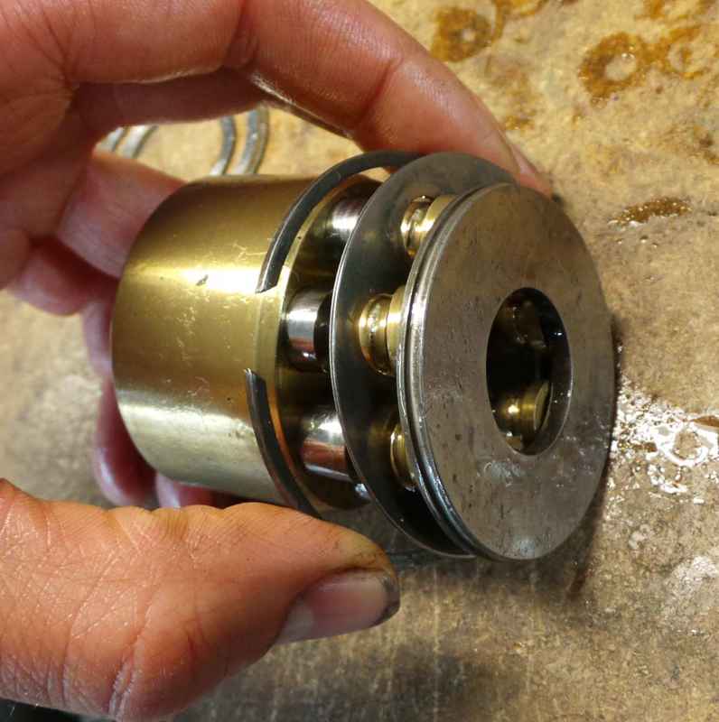
Here's how the pistons and piston retainer collar all go together and ride on the piston cup raceway which goes against the swashplate end plug.
Above:
More.
Above:
Again, but showing the swashplate collar retainer snap ring
Above:
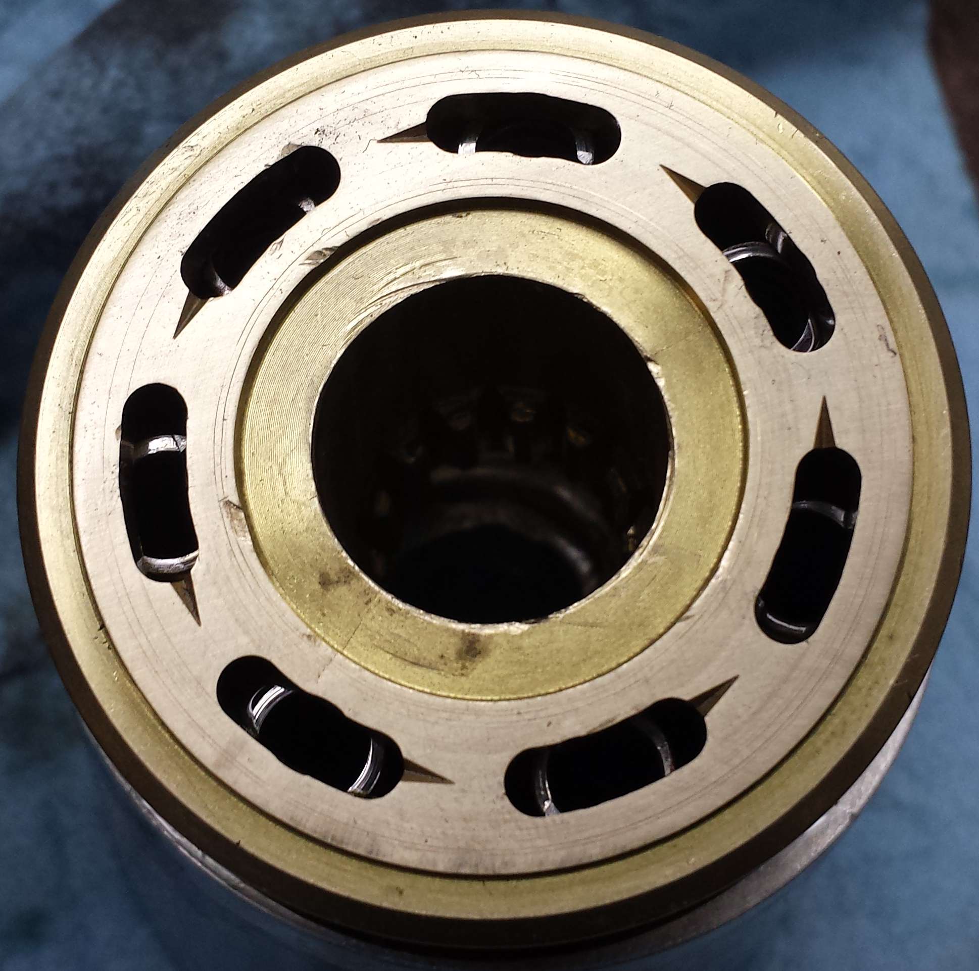
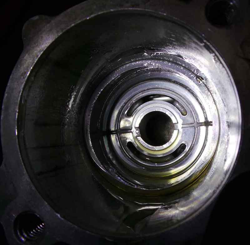
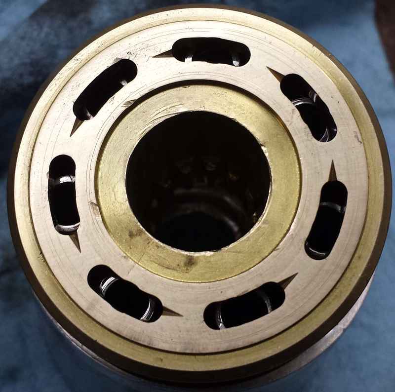
The valve face of the rotating brass cylinder core.
Above:
Very important:This shows the correct rotational orientation of the swashplate end plug. You can't see it, but the brass cylinder and
all the springs and pistons and piston collar and piston collar retainer are all assembled and inserted into the swashplate endplug with the hard
smooth steel piston cup raceway plate.But you can see the end of the bolt and the nut that's holding the whole spring loaded assembly together for assembly.
In our case, the oil hole was on the thick side of the swashplate. (The bolt that holds on the fuel pump was the perfect size in our case.)
In the pump housing, the inlet is on the right, and the outlet on the left, and looking at it from the back as is pictured above, the pump turns clockwise,
so the pistons need to be sucking in oil as they travel down the right side, and pushing out oil as they rise up the left side. Thus, the thick part of the
swashplate pump must be on the top in the picture.
You can see that the inlet has a single passage coming in, but the outlet has two passages. One goes up to the top left to the spring pressure bypass,
and the other goes to the bottom left to the pump's output fitting (bottom) and the IPR valve (lower left.)
The IPR valve controls the quantity of high pressure oil that can bypass back to the inlet of the pump in order to control the output pressure.
Above:
There you can see the steel valve face plate. Note that it is keyed but one key is bugger so it only goes in one way - just be sure to get the correct face out!
03/13/2015